K-zell Metals offers tube bending and mandrel tube & pipe bending services. We also offer custom tube bending services for tube rolling, round tube, square tube, bar and pipe. We are here for your custom metal bending needs.
Part Design Best Practices when Tube Bending is Required:
There are several different processes for bending tube, and those process vary with machines and tooling. A couple of the most common methods are Rotary Draw Bending and Push Roll Bending. The differences between the two pertain exclusively to the requirement of the centerline bend radius of the tube (this can also be applied to other structural shapes like, angles, channels, I- Beams, T’s, etc).
The general rule to determine which type of bending process is required is based on the bend radius divided by the tube/angle/channel cross section dimension. If the centerline bend radius of the part is less than 8 times the material cross section then Rotary Draw Bending is the required process; if the radius is greater than 8 times the cross section (also known as an 8D bend) then push rolling is the correct process.
For Example:
1” OD Round tube with a centerline bend radius of 3” requires Rotary Draw Bending (3” Centerline Radius / 1” OD Tube = 3 or 3D Bend)
1” OD Round tube with a centerline bend radius of 12” requires Push Roll Bending (12” Centerline Radius / 1” OD Tube = 12 or 12D Bend)
One you have determined the process by which to accomplish the bending of the part there are other design consideration as it pertains to each process:
Rotary Draw Bending; < 8D bends:
Bend Radius Determination:
One of the most important considerations of part design when Rotary Draw Bending specification is required is the bend radius (FYI, we are always taking centerline as a standard) relative to the material alloy. The minimum bend radius that an alloy can tolerate has to do with the elongation % of that alloy. As an example, typical Hot Rolled ASTM A513 ERW (Seam welded mild carbon steel tube) has a range of elongation but as a minimum, runs about 25% - 30% (Mill Test Reports will usually note this specific to the tube when purchased). This elongation allows for a relatively small D bend usually on order of about 2D – 3D. On the other side of the spectrum is 6000 series aluminum (6061-T6 and 6063-T52) which has a typical minimum elongation % of 10% - 12% meaning that a minimum bend is around 4D – 5D to avoid fracturing and breaking. Generally speaking you will find that the MTR’s (Mill Test Reports) of 6000 series aluminum tube will have quite a bit higher elongation % than what the typical minimums are but it is always dangerous to design around the upper end of the available elongation % as that material can become sparse or non-existent over time which may require heat treatment before and after forming (annealing and solution treating) which will add considerable time and cost to a part.
300 Series stainless steel on the other hand has a relatively high elongation of 40% - 60% in most instances meaning you can design just about any radius size you want.
Also, as part of the discussion about bend radius definition is the factor of Radial Growth Compensation. There is a zone from about 4.5D up to 8D where radial growth compensation is required even though the tube is being formed around a fixed tool bending die. This has to do with the material alloy and how it behaves when you apply enough force to take the material past it’s yield point and the location of the bend turns into a plastic state. During all bending and especially Rotary Draw Bending the outside of the tube (farthest point from the bend die) stretches conversely the inside portion of the tube (closest point to the bend die) compresses. During smaller D bending (<4.5 typically) the changes aren’t as significant as it pertains to radius growth but on the larger D bends these factors play a larger roll meaning the bend die tooling has to be compensated for the radial growth. The consequence to specifying a large D bend usually means that custom tooling must be produced, and that tooling is also specific to the alloy of the tubing. Typical bend die costs range from $1200 - $3500 so the impact can be significant unless the production run or the lifespan of the product is significant.
Tube Size & Wall Thickness:
Another variable to consider when designing parts that require Rotary Draw Bending is the tube cross section size to wall thickness ratio in relation to the bend radius. Generally, as the tube diameter increases, and the wall thickness decreases the harder it becomes to produce a small D bend. These conditions require additional tooling to be successful such as mandrels with higher ball (movable segments of the tube ID profile attached to the end of the mandrel) counts and even the use of a wiper die. The uses of the mandrel for tube bending is needed to maintain the tube shape and prevent distortion whereas the wiper die is required to apply pressure just in front of the tangent of the bend die. The pressure that the wiper die imparts on the tube is meant to help prevent bunching or rippling of the inside portion of the tube; the zone where compression of the wall takes place. Wiper dies are specific to tube size and bend radius and are also considered a consumable as they will wear overtime and need to be replaced. Tooling always has an expense so avoidance of the need for a wiper die can help to control costs of manufacturing a part. Mandrels can also wear over time and need to be replaced, especially on the harder alloys.
Part Tangents / Straight Distance Between Bends & Grip Length:
The last two significant design characteristics to be aware of is the distance from the end of a tube to the start of a bend and the straight / tangent distance between bends. The importance of these dimensions’ stems from the way the process of rotary draw bending works. A rotary draw bending machine uses an arm that rotates in a single direction during bending but before it can rotate and bend the tube the clamp die must be engaged.
To understand the importance of the tangent length on a tube the following is a typical simple sequence of part processing:
#1: The tube is loaded manually or automatically and captured usually by a collet or clamping devise of some kind.
#2: The tube is then positioned (manually or automatically) in the bend die.
#3: The clamp die is moved in to hold the tube to the bend die.
#4: The pressure die moves into place behind the bend die (this can be nearly simultaneous with the clamp die positioning).
#5: Machine arm rotates, and the bend is complete.
If the distance from the end of the tube to the start of the bend is too short relative to the tube diameter then there is a potential for the tube to slip during the rotation of the machine. As a rule you want the distance from the end of the tube to the start of the bend to be at least 3 times the tube cross section diameter (we call this Grip Length) to be certain that slipping will be minimal to nonexistent. The length of the Clamp Die almost always matches the Grip Length value.
If a 3X distance (Grip Length) is not reasonable there are options such as specially fabricated knurled clamp dies that can be produced in shorter lengths. This knurling creates a greater amount of friction to avoid the potential for slipping but has the consequence of being more expensive than a standard bend die, will wear over time and need to be replaced (usually just an insert), and will also leave heavier tooling marks in the part which may need to be addressed with a downstream process such as grinding or polishing (adding cost).
The same concept of minimum Grip Length / Clamp Die length applies to the issue with the distance of tangents between two bends. The distance between bends should be equal to or less than the Grip Length of the bend die otherwise the tooling will interfere with the previous bend and create a heavy tool mark or worse a dent in the tube. When designing around this minimum Grip Length is not possible special compound Bend and Clamp dies are required. Pricing for these specialized tools are in the thousands of dollars so again the production volumes or part lifespans must justify the investment costs of these custom and mandrel tube bending tools and services.
Push Roll / Roll Bending; > 8D Bends:
Bend Radius Determination:
Like the Rotary Draw Bending there is a zone that presents unique challenges to the Push Roll / Roll Bending process. Centerline radius bends from 8D up to 16D can be difficult to nearly impossible to accomplish without significant distortion. That distortion can manifest in ripples produced on the surface of the tube, change of dimension of the tube profile, flatness issues after forming, ect. The degree of this distortion is relative to the material alloy, the section wall thickness, and how close to the 8D value you are rolling to. The closer to the 8D value the greater degree of distortion that will be present and the more time and money a part will cost.
There are specialized tooling and CNC bending machines that can greatly reduce this distortion (such as our Horn 65TBRE Machine) but there needs to be enough production quantity to justify the initial programing, set up, and scrap rate costs to justify the process selection.
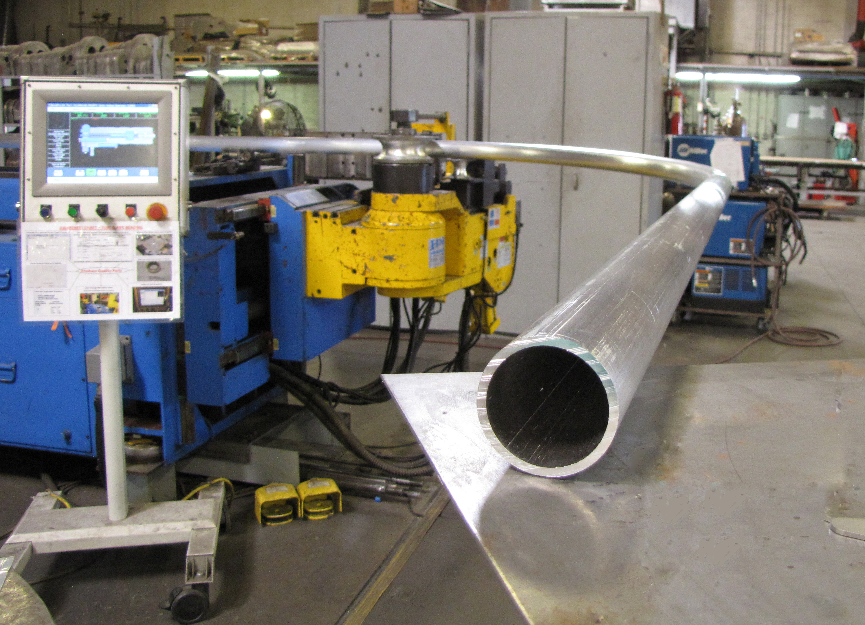
K-zell Metals has a Horn Metric 65TBRE CNC tube bending machine with both rotary draw bending and push roll capabilities. It is a two-stack machine and can accomplish both types of forming on the same part, in a multiple step process.
A good step to minimize the tooling costs associated with tube bending is to at the beginning of your design process reach out to fabricators that potentially can do your work. Discussion with the fabricator can establish what materials, tooling and capabilities they have to help you with your project. For instance if you were planning on a 2-1/2” centerline radius but the fabricator has a 2-3/4” centerline radius tooling instead, and your design is in the early stages, it can be modified to accept that new radius with minimal impact. This type of change could save you several thousand dollars in tooling costs.
K-zell Metals welcomes these discussions.


CNC Tube and Pipe Mandrel Bender Services
Watch this video that shows forming 2” schedule 40 (2-3/8” diameter x 0.15” wall) 6061-T6 Aluminum pipe to a 46” centerline radius on our Horn Metric CNC Tube bender:
65 MM Horn Metric CNC Tube Bender
- CNC control of bend angle, distance between bends and angle of rotation between bends
- push roll capable
- 2 stack tooling
- 20 foot mandrel
- Automatic mandrel extraction
- Mandrel lubrication systemWell tooled